The SPI bus is a high-speed serial bus that connects a master device to one or more slave devices. In this project, the AT90 is the master and the nRF24L01 is the slave. All communications are initiated by the master. The SPI protocol behaves like a ring buffer, so that whenever the master sends a byte to the slave, the slave sends a byte back to the master. The slave can use this behaviour to return a status byte, a response to a previous byte, or null data (the master may choose to read the returned byte, or ignore it). The bus operates on a 4-wire interface as follows:
- Slave Select (SS, also referred to as CSN, NCS, NSS, CTE) selects which slave should listen on the bus. Many slaves can be connected to the bus (they share the other three wires), but only one can be selected to communicate at a time. The slave select is active-low.
- SPI Clock (SCK, also referred to as SCLK, CLK) carries the clock signal that synchronizes the master with the active slave. This wave is sent by the master; it is generated automatically by the AT90’s SPI module during an SPI transaction. It determines the speed at which the SPI connection transmits data.
- Master Out Slave In (MOSI, also referred to as SIMO, SDI, DI) carries data bits from the master to the slave.
- Master In Slave Out (MISO, also referred to as SOMI, SDO, DO) carries data bits from the slave to the master.
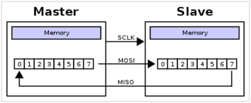
4-wire SPI is a full-duplex protocol, although the slave cannot initiate a data transfer. The slave must alert the master that it has data ready using some external mechanism, such as an external interrupt, so that the master can initiate the transfer. The SPI protocol uses a 2-word ring with one word on the master and one on the slave. To send a bit, the master shifts the bit out of its buffer onto the MOSI line and ticks the clock. The slave shifts its next bit out of its buffer onto the MISO line, and shifts the MOSI line into the buffer. This process is done eight times to transfer a byte (unlike UART, the protocol doesn’t use start or parity bits). The following image (source) shows how bits are shifted around the 2-byte ring:
Configuring the SPI module on the AT90 is very easy. The SPI pins on the AT90 must be set to the correct direction, and the SPI control register SPCR must have the SPE (enable) and MSTR (master mode) bits set, and all other bits cleared. Some slaves may need the SPI module to be configured differently (e.g. different phase or polarity on the clock), but this is how the bus is configured for the nRF24L01. This leaves the SPI prescaler at its default of fosc/4, which is the maximum speed recommended in the AT90 hardware manual (p. 173) when the AT90 is acting as a slave. When the AT90 acts only as a master, the maximum prescaler value of fosc/2 can be used safely. The faster transfer rate is enabled by setting the SPI2X bit in the SPI status register SPSR.
The driver assumes that the AT90 does not act as a slave, and sets the SPI speed to fosc/2; this can be disabled by commenting out the corresponding line in the SPI_Init function in spi.c. Using fosc/2 on an 8 MHz microcontroller, the SPI bus operates at 4 Mbps. The nRF24L01 supports an SPI connection of up to 8 Mbps, so even with a 16 MHz crystal added to the AT90 and the SPI prescaler set to fosc/2, the nRF24L01 will work properly.
Sending a byte over SPI from AVR is accomplished as follows (assuming the SPI module has been initialized):
- Set the slave’s CSN pin low to enable SPI on the slave.
- Write the byte to the SPDR register.
- Wait for the SPI Transfer Complete interrupt to be triggered, either by using the interrupt vector (SPI_STC_vect) or by polling for the SPIF flag in the SPSR status register; the radio driver uses the polling method, since the transfer only takes a few cycles to complete.
- To get the byte that was shifted from the slave into the master, simply read the SPDR register. This value may be ignored if the return byte isn’t useful.
- If there are more bytes to transfer, return to step 2 for the next byte.
- Set the CSN pin from step 1 back to high to end the transaction.
See the page on firmware for some examples using SPI.