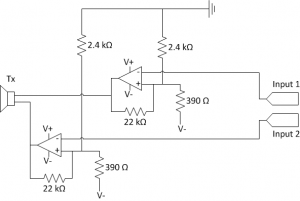
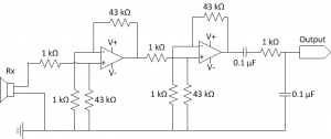
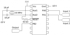
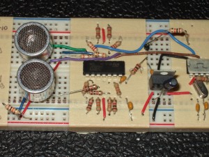
Here are some circuit diagrams (leaving the power source abstract):
Monthly Archives: January 2011
Low-rent acoustic receiver
I’ve previously described the power supply and transmitter for my acoustic modem.
The receiver circuit completes the modem’s hardware design. It is simply a two-stage amplifier that gives a total gain of about 2000, in series with a band-pass filter.
The acoustic transducer produces a beautiful sine wave with nearly no noise. I found that I could apply a huge gain to its output and the amplifier’s output would still be clean: the raw (unfiltered) output has a 5 V offset, and the signal fits into the 5 V above the offset. In other words, the output is at -5 V when idle and peaks at around 0 V when the receiver receives a signal.
The goal is for the receiver to output a signal that is around -10 V when idle and peaks at -5 V when it receives a signal. These voltages correspond respectively to logic low and high on the microcontroller.


