Tag Archives: overengineering

Waterproofing 3D Prints (and also making them look super-cool) with Epoxy Clay

It’s pretty hard to get a watertight object out of our Makerbot Thing-O-Matic.  The walls of printed objects are pretty solid, but unexpectedly porous; even a thick block printed with 100% infill will allow water to penetrate it due to errors around the edges and imperfectly fused strands of plastic.  If you want to make a hollow object waterproof you’re going to have to do some post-processing.

It gets worse when the object is a curved surface, as is my AUV hull.  I’ve read that objects can be made watertight by adding outer shells.  That may be true for some objects, but on objects that curve along the z-axis the number of shells exposed to the surface grows as the tangent plane gets closer to parallel to the printer’s build platform—and big holes start to form.

My hull doesn’t actually have to be watertight, it’s a wet hull.  But it has to be airtight in order to hold the bubble of gas that controls the robot’s buoyancy.  Here’s what the airtight hull looks like:
Continue reading

Un-improving range on the infrared channel

It turned out doing software UART was a terrible idea.  The processor is way too slow to support a reasonable baud rate.  I did figure out how to use a comparator though: the key phrase I was missing was “rail-to-rail.”  That means that inputs can be in the full voltage range from ground to Vcc.  Another handy phrase is “push-pull,” which means that the comparator can output 0 and 1; in contrast, an “open collector” comparator can only output 0, and needs an external resistor to pull the output to 1.

I bought a rail-to-rail push-pull comparator, the MCP6541, and tried it with the receiver circuit, and sure enough it increased the maximum range significantly.  Unfortunately it also increased the minimum range significantly.

Continue reading

Improving range on the infrared channel

The range on the infrared channel, which I discussed in the last entry, is probably enough; but I’d like to increase it a bit.  With more range I can space modules farther apart if needed, and hopefully be able to have a wider angle between the transmitter and receiver.

Fortunately the signal output by the Darlington transistor pair on the receiver is a pretty clean digital signal.  At full power it ranges from (a little above) 0 V to (a little below) 3.3 V.  As the transmitter gets farther away the digital signal remains but the low voltage increases beyond the UART receiver’s ability to read a 0.  For example, at a large distance the UART signal might range from 2.5 V (logical 0) to 3.3 V (logical 1).

There are several options I’ve considered:

Continue reading

How I’m powering my acoustic modem

Power supply

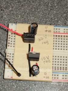
A ±10 V power supply

I’ve covered how not to power an acoustic modem, and how I’d like to power an acoustic modem, now it’s time to tell how I’m doing it right now.

To restate and clarify the problem: I want to use an acoustic transducer to transmit and receive data via pressure waves.  The transducer I have transmits a 40 kHz carrier wave, and can be driven by up to 20 V.  That means that when transmitting, the circuit must alternate a 20 V signal back and forth between the transducer’s two input pins, once every 25 microseconds.  Additionally when receiving, the transducer’s output signal needs to be amplified into a usable signal. Continue reading

How not to power an acoustic modem

crummy power supply

How not to generate a ±10 V power supply

I feel pretty dumb talking to nobody like this.  My domain name doesn’t even work yet, but I guess logging is what engineers do.  And I’m imaginative enough to see the utility of it: it’ll be nice down the line to have a log to review, writing stuff down helps flesh out ideas, and an open design process will make it a heck of a lot easier to produce open documentation.  It will be tough to expose all my bad decisions and half-baked ignorance (and mixed metaphors), but I can suck it up.

My first project is to build an acoustic modem.  This follows the principle of multiplying work: the modem doubles as my class project for ELEC 571: Underwater Acoustics.  We’ve been using the Devantech SRF04 ultrasonic ranger in the mechatronics lab, and it strongly informs my design.  The SRF04 actually uses an RS-232 chip to generate ±9 V levels, which actuate a piezoelectric transducer.  I took a couple of the transducers from a broken SRF04 to use for my project.

I tried using an RS-232 chip that we had lying around in the lab, but those things have draconian current limits.  There’s no way I can power a whole circuit off of one.  I’m probably going to try it again soon though.

My solution: a DC/DC converter (AP34063N8L) to step up a 7.4 V lithium polymer battery up to 20 V.  Taking half the output as the reference voltage will produce a ±10 V power supply.  With that I can power pretty much anything I want. Continue reading