Monthly Archives: December 2010

Ruminations on guitar tuner mkII

Moooooooo.

The old guitar tuner I made works fine, but I’m thinking of some improvements:

  • The first priority is to switch the power supply from a 16 mm coin cell to a 20 mm coin cell.  20 mm cells are way easier to find: the dollar store down the street carries 2032 cells (2032 means 20 mm diameter, 3.2 mm height), but 1632 cells are expensive and hard to find.  Right now I’m clamping a 3x AA battery holder to the tuner’s + and – power pins, which is not comfortable.
  • The rotary switch is too expensive.  A 0.1″ two-row header with a jumper to select the tuner’s frequency will be cheaper, and won’t be an ugly blue box.  This is still not as flexible as the 7-segment display the original project used.
  • I’d like to use a low profile DIP switch to turn the power on and off instead of (or in addition to) mucking around with sleep mode.
  • It would be cool to use a surface mount microcontroller and crystal.  Getting an STK 600 routing card for 14-pin SOIC AVR chips might be worth it if I find money somewhere.

I considered replacing the microcontroller with a 555 timer, but I don’t think the 555 timer will generate sufficiently precise frequencies because of the tolerances in the resistors and capacitors.
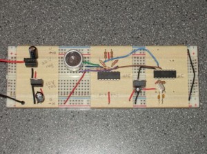
Low-rent acoustic transmitter

Acoustic transmitter circuit

Acoustic transmitter circuit.

Above you can see the transmitter part of my acoustic modem.  From left to right, the components are: the power supply, the acoustic transducer, the amplifier, and the microcontroller.

The problem: I need to send a 40 kHz, 20 V peak-to-peak square wave to the transducer.  The circuit has two outputs, + and -, that are connected to the two transducer pins.  In other words, each output needs to switch from +10 V to -10 V  and back once every 25 microseconds.

As always, there are a few decent solutions, and as always I didn’t implement the best one.

Continue reading

The Schmitt trigger

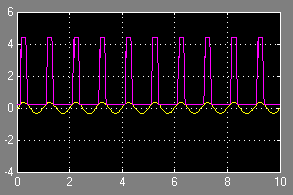
Schmitt trigger example

Simulation of a Schmitt trigger. The yellow sine wave is the input, the purple square wave is the output.

I was looking for a way to convert an analogue signal into a digital signal, and came across the Schmitt trigger.  This is a great little circuit that you can build with a couple transistors or with an operational amplifier.  I tried to build a transistor-based simulation in Simulink, but it didn’t work right away.  My op-amp simulation did work, so I stuck with that.

The principle is simple: if the trigger input rises above a certain threshold, then the output saturates to the op-amp’s positive power supply voltage.  When the input falls below another threshold, the output saturates to the op-amp’s negative power supply voltage.  If the input lies between the thresholds then the output doesn’t change from whatever it was before.

This is incredibly useful.  To the left you can see a 0.3 V sine wave being converted into a 5 V binary signal (actually a 4.5 V signal, since I added a diode in series with the output to keep it from going down to -5 V).  It also effectively filters out any input jitter that doesn’t cross the threshold needed to change the output state.  Microcontrollers have Schmitt triggers on their digital inputs.  For example, an AVR microcontroller being powered by 5 V typically considers a 0 logic level to be under 1.5 V and a 1 logic level to be over 3 V.  If the input sits between 1.5 V and 3 V then the digital state remains whatever it was before the input entered that region.

Alas, it’s not a perfect circuit.  I used an online calculator to figure out what resistances I needed for my project.  Configurations that worked in the calculator and in simulation didn’t work in reality, either producing no output or something more like a sawtooth wave than the square wave I expected.  It’s probably a limitation in my op-amp—maybe the signal is too high-frequency, I didn’t investigate very deeply.