Update Jan. 10, 2013: This page talks about the Replicator 2, which we don’t have yet. It should get here in February. In the meantime you can use the Thing-O-Matic.
3D Printers
3D printers are used to convert 3D models on the computer into physical objects. This is super-useful in our lab: students often need to make customized parts for their robots, and the 3D printer lets you rapidly design and create many of the parts you’ll need.
There are a lot of different kinds of 3D printer. The CNC machine like those in the mechanical engineering machine shop are traditional 3D printers. There are expensive printers like the ZPrinter that build up objects by fusing powder particles together. Other printers based on open source hardware sacrifice resolution, process and build quality, and other properties to drive down prices into reach of regular people (and impoverished software engineering labs). RepRap was the first open source 3D printer, Makerbot sold the first full 3D printer kits, and in the last couple years several companies have started selling derivatives of those designs. Popular 3D printers include the Ultimaker, Printrbot, Prusa Mendel and the Type A Machines Series 1. All these printers print in a variety of plastics. The bleeding edge of open source 3D printing is projects like the B9Creator and the Form1. Both printers print in resin that hardens when exposed to bright light; the former uses a DLP projector to harden layers of resin, and the latter uses a laser. This process allows a high resolution, very high precision, and more freedom of design than RepRap-style printers.
In ECS 366 we have two Makerbot 3D printers, a Thing-O-Matic and a new Replicator 2. This page will give you the information you need to get started using the 3D printers to make parts for your projects.
Model Design
The first thing you need to do is generate a 3D model of what you want to print. The model needs to be a 3D mesh in STL format. Most 3D design software can export to STL.
Software
There are a bunch of software tools you can use to create a 3D model.
- Autodesk 123D: This is my preferred 3D design tool. It’s free and pretty easy to use. 123D is a legit CAD program, so you can easily input precise dimensions. Autodesk has put a useful series of tutorial videos on Youtube. The downsides are that it is Windows-only, and it’s beta software (still a little slow and unstable). Note that as of Beta 9 you need to log into an Autodesk account inside the program in order to print the model to an STL file. If you have stability problems try installing the latest drivers for your graphics card.
- Autodesk Inventor Fusion 2013: Similar to 123D, but more powerful (and commensurately harder to use). There’s currently a free technology preview available for Mac.
- Blender: Blender is a popular tool among the 3D printing community, partly because it’s open source and works well on multiple platforms. It’s more of an artistic tool rather than a CAD program, and it’s also extremely difficult to use if you’re inexperienced with it. It can be used to convert many model formats into STL.
- OpenSCAD: Rather than editing a model directly, with OpenSCAD you write code and compile it into a 3D model. This is also quite hard to use because you have to learn a new programming language. On the other hand, you can implement your program using parameter variables and just change those variables when you want to adjust the model, which makes design iterations potentially a lot faster. The program comes with a lot of example code, and there are a lot more examples on Thingiverse. The official documentation is generally unhelpful.
- 3DTin: A free, browser-based (and therefore multi-platform) design program. It’s not as flexible as other programs, so it’s more suitable for simple designs, but it’s not useless and it’s good for learning 3D modelling.
- Cadmium: A Python library for solid modelling. It’s a lot like OpenSCAD, except you write Python code. The downsides: it doesn’t come in a friendly installer package, and it doesn’t include a model viewer. Also I suspect it’s a little less functional than OpenSCAD.
- Sculptris: A program for “sculpting” meshes like clay, not great for engineering design but pretty cool for artistic stuff and good for smoothing meshes (e.g. from 3D scans).
- Sketchup: Kind of hard to use for engineering or art. I don’t recommend it, as it’s not a solid modeller and will occasionally add internal geometry that causes flaws in the printed object that aren’t apparent in the model. It does not support STL natively, you need a plugin. However, a lot of people seem to have used it so I thought I’d mention it.
- Autodesk 123D Catch: This is a companion program to 123D that can be used for 3D scanning. You just take a bunch of photos of an object, load them into Catch, and after a little while it sends you back a textured model of the object that can be edited and exported as an STL.
- Solidworks: A commercial CAD suite. This is taught to mechanical engineering students at UVic. It’s not unlike 123D in terms of basic functionality, but it has a lot of advanced features and it includes an OpenSCAD-like programming system. Non-mechanical engineering students can access Solidworks in ELW 307 (the Engineering Dean’s lab).
Design Constraints
The Makerbot uses a fused filament fabrication (FFF) process, which means that it constructs a model by depositing melted plastic strands that stick together as the material cools. When hot plastic is deposited on the warm layer below the layers fuse into an object. The nature of this process imposes some limitations on what you can print.
The printer can position its toolhead fairly precisely, but the strand width, which determines the minimum feature thickness and layer height, is large. On the Thing-O-Matic the minimum feature thickness is about 0.5 mm and the layer height is about 0.4 mm. The Replicator 2’s minimum feature thickness is about 0.4 mm and its layer height is adjustable from 0.1 mm to 0.35 mm. When designing your model, try to make its x and y dimensions multiples of the minimum feature thickness, and its z dimensions multiples of the layer height. If you don’t the final physical dimensions may be off.
The plastic strand comes out melted, so if the printer tries to print over open air the strand will droop, or even fall down if it’s not supported on one side. There are a couple ways around this limitation. First, as long as an overhang is more than 45° above the x-y plane it should be okay, if a little rough. You can also add supports for overhangs by adding a strut at no less of an angle than 45°. You can also support a cantilever or similar overhang by adding a 1-strand-wide (0.5 mm wide) support shell around its outline. The shell it built up from the bottom layer and the part is printed resting on the shell, then the shell can be cut away with a utility knife when the object is finished. See here and here for more information on building supports into your model. The printing software also includes the option for automatically adding supports to the model. Sometimes it’s easier to let the software do it for you, sometimes you can save print time and reduce material waste and surface roughness by designing supports yourself. Here is an example of a model that was printed with automatically-generated supports, here is the model after the supports were removed.
If there’s too little material in a layer, the toolhead will slow down to give the layer time to cool down a bit and settle. On the other hand, if the layer takes too long to print (i.e. the layer is too big) the plastic can cool off too much, and the next layer won’t fuse to it very well.
Fixing up the STL File
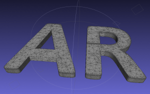
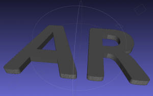
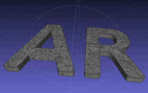
Sometimes your modelling program generates an STL file with some flaws. For example, 123D (as of beta 9) doesn’t focus its polygons optimally, putting too many triangles on flat surfaces and/or too few on curves. It’s not always a big deal to have too few triangles since the 3D printer is pretty low resolution, but if curves are triangulated poorly it can be obvious in the final output. It’s not good to have a lot of triangles either, because more triangles means it takes longer to process the STL model before printing it (sometimes 123D produces way too many triangles, even on its coarsest setting). One solution to the problem is to generate the STL file with too many polygons, and then use another tool to reduce the polygon count intelligently. MeshLab accomplishes this task effectively. Import the STL mesh file to MeshLab, and open the Filters | “Remeshing, simplification, and reconstruction” | “Quadric Edge Collapse Decimation” dialog. The dialog automatically selects half the number of faces that are in the original model, and you can tune it manually. Hit the Apply button, and if the model still looks okay then you can export the mesh (select “Flat Lines” mode to see the polygons).

Low-resolution model decimated further to 20,000 triangles. Note that the polygon density on flat surfaces is much lower than the polygon density on curves.
MeshLab doesn’t always produce good output, especially if you remove too many polygons. ReplicatorG sometimes complains if the mesh that MeshLab produces is not manifold, meaning that there’s a hole in the mesh and it’s hard to tell the difference between the inside of the object and the outside. This complaint happens with the output from other tools as well, particularly Google Sketchup and Blender if you’re not careful. Skeinforge can usually figure out what to do after a bunch of number crunching, but you can help it out by running the STL file through the STL repair tool at netfabb. N.b. the netfabb tool will destroy any internal geometry and small holes that you might have purposely designed into the model. Meshlab can also mess up the decimation process by adding surfaces with 0 volume, I have no idea why it does that or what you can do to fix it. Because of the potential problems with using Meshlab I recommend avoiding it if possible, but it can be very useful in some situations.
Plastic Types
Our Makerbots use different types of plastic: the Thing-O-Matic prints in ABS, the same plastic that Legos are made from; and the Replicator 2 prints in PLA, a biodegradable material.
Different ABS spools have different physical properties. In particular, plastic from different spools might melt at different temperatures. There can be a variety of causes, including the extrusion process and colourants. Most colours we have flow well at 225°C. Some colours, notably our current black plastic, don’t flow well until the temperature reaches 235°C. At 225°C the black plastic prints but the model layers don’t fuse well and the output is unreliable (it misses parts of strands). Unfortunately turning up the temperature releases stinkier fumes (as far as I can tell the fumes are safe at the temperatures we’re using, but some people may be more sensitive to the fumes than others). You can open a window to help clear out the fumes, but make sure the air in the room doesn’t get too cold, or it will cool the plastic too quickly and the model’s layers won’t fuse together well.
PLA melts at a lower temperature than ABS (usually around 190°C or so), and burns if the temperature is too high. It does not flow as smoothly, and is less compliant at room temperature. It dissolves in acid.
Operating the Thing-O-Matic Using ReplicatorG
Configuration for First Use
These steps only need to be performed once per username.
- Under the Machine menu, open the Machine Type (Driver) submenu and select Thingomatic w/ HBP and Stepstruder MK6 (Sailfish)
- Under the Machine menu, open the Connection (Serial Port) submenu and select COM3
- Under the GCode menu, open the GCode Generator submenu and make sure Skeinforge (50) is selected.
- Press the Connect button (looks like a plug with an arrow pointing left). The status bar should turn from red to green.
Printing Process
- Start ReplicatorG. If you’ve configured it using the steps above, it should connect automatically and show a green status bar.
- Open the control panel (a toolbar button that looks like four arrows in a cross formation).
- Start the heating procedure by setting the extruder temperature to 225 and the build platform temperature to 125. You have to press the enter key after entering the temperatures for them to be set properly.
- Home the axes using the Homing menu. Home the Y axis before the X axis. Now you can go back to the main RepG window and proceed.
- Load the STL file you want to print (see below for more information).
Generate the GCode (see below for more information).
- When the GCode has been generated and the temperatures have reached their set points, hit the Build button in the RepG toolbar (it looks like an arrow pointing rightwards to a peanut for some reason).
- If you didn’t wait for the printer to heat up or home the axes, it will do so now.
- Make sure the brass weight is resting on top of the printer. We don’t apply the weight until it has started to print, so as not to affect the Z travel.
- Once the print job has started, lower the brass weight.
- Watch the first layer of the print carefully. If necessary, use the little screwdriver to rescue the extruded plastic strand from sticking to the toolhead or from curling up away from the build platform.
- Don’t leave the printer unattended for very long. It’s a bit of a fire hazard.
Loading the STL File
- Go to the FIle menu, and select Open…
- Browse to the STL file you want to print, and open it.
- The model should display in RepG’s main window. If it doesn’t select the “View” button, and click and drag the main window. The model should now display.
- Select the “Move” button and click the “Center” button that appears. The model will be placed on the platform at its centre.
- Use the “Move,” “Rotate,” “Mirror,” and “Scale” buttons to adjust the model as necessary.
- When the model is ready, save the STL file by pressing CTRL+S.
Generating the GCode
The GCode generation settings are persistent across runs of RepG. Some of them (steps 2 and 4-7) you can skip after you’ve done them once. Others (steps 3 and 8-11) you might change, depending on what you’re printing.
- Press the “Generate GCode” button.
- For the Slicing Profile, select <whatever the correct entry is>
- Unless you want the object to print with a raft, make sure the “Use Raft/Support” checkbox is unchecked.
- Ensure the “Use default start/end gcode” and “Use Print-O-Matic” checkboxes are checked.
- In the Settings tab, set the Layer Height to 0.4 mm. Leave the Number of Shells set to 1.
- In the Plastic tab, change the Filament Diameter to 2.9 mm.
- In the Extruder tab, change the Nozzle Diameter to 0.5 mm.
- In the Settings tab, set the Object Infill percentage. This controls the density of the inside of the object. A lower infill (e.g. 10%) means the part is lighter and uses less plastic, but is also weaker and won’t support surfaces as well. A higher infill (e.g. 35%) will support the top of the object better and make it stronger, but it will take longer to print the extra filling. There’s not much point in going higher than 35%.
- In the Settings tab, set the Feedrate speed. This controls how fast the toolhead moves when it’s extruding plastic. A normal value is 30 mm/s. Slow it down to 20 mm/s to get a slightly better print. Speed it up to 45 mm/s to go faster at the cost of slightly lower quality. Any value over 40 mm/s will result in a warning that acceleration must be turned on. You can ignore that, since we have acceleration enabled. I haven’t exceeded 45 mm/s, you can try but don’t be too ambitious; higher speeds can damage the machine.
- In the Settings tab, set the Travel Feedrate speed. This controls how fast the toolhead moves when it’s moving between extrusions. This can be set higher than the printing feedrate, but be aware that sometimes when the toolhead is traveling it can drag across the object and might damage it or ruin the print if it’s going too fast.
- In the Settings tab, set the Print Temperature. This is the extruder temperature. 225 (units are °C) is a good value for all of our plastic except for the black. For the black, use 235.
- Press the “Generate Gcode” button and wait.

