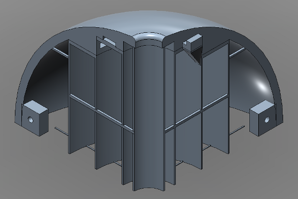
I printed four copies of the semidemihemisphere and refined it a bit as I went. Here’s the whole thing, including the hull that I covered in my last log entry. The only difference in the hull is I removed the top hole, as only two of the semidemihemispheres need it (as valve mounting holes).
I made a few interesting changes to the cutaway portion though:
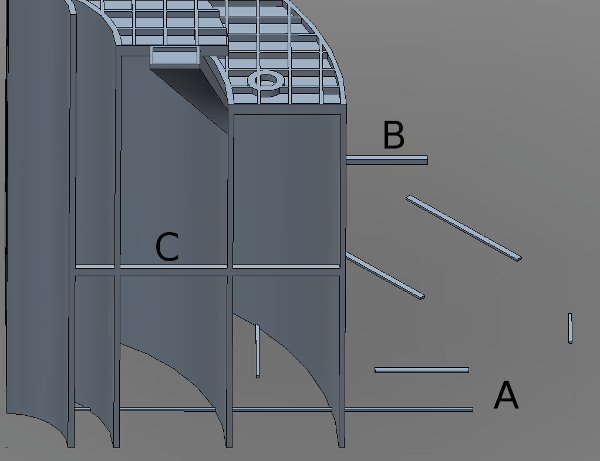
The cutaway is needed to hold up the hull while it prints. Without the cutaway, the plastic, heated to its melting point by the Makerbot, will droop and hang or fall. The cutaway gives the hull something to sit on as the plastic cools. Here is the cutaway portion, viewed from the side:
A – I added a bunch of little bits on the bottom layer of the model. This is a hack to get the printer to print a larger raft. (The raft is a thick layer of plastic that the model sits on as it prints, intended to let the model stick well to the build platform.) I had to reduce the raft margin so that it would fit on the build platform, but with the smaller raft the pieces were susceptible to being knocked around by the toolhead as it goes. These pieces get raft added around them, which merges with the raft of the actual model so that the real pieces get a nice stable raft.
B – This bit connects the cutaway material to the hull. The hull is getting pretty tall at this point, so if it gets hit by the toolhead there’s a force applied that is strong enough to knock around the hull and perhaps misalign the layer. This part (and its equivalent on the other side of the model) help hold the hull steady against the cutaway shells as they get close to being joined together.
C – This bar connects the cutaway shells together to keep them steady. In a previous model (shown in the last log entry) I made this part too wide, and it took so long to print the horizontal bar that the hull cooled too much and split a little. It wasn’t anything a little plastic welder couldn’t fix, but the supports don’t need to be very wide to fulfill their purpose. After shrinking them to 1 mm wide the printer could print one bar layer with just two quick strands of plastic.
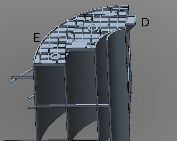
D – This is the support for the upper tab that hangs freely over the semidemihemisphere. You can see it from the side at the top of the cutaway side image above. This is a pretty cool piece that’s anchored vertically on the cutaway shell, and ends up a horizontal flat surface at the upper tab bottom. It is topped by a 0.5 mm shell that the tab sits on (see E). I did this piece with a loft from a rectangle on the vertical plane to a rectangle on the horizontal plane.
E – The lattice pattern holds up the hull’s overhang. The lattice rests on a 2-layer thick platform. The bottom layer of the platform is printed over open space, and droops badly. The second layer of the platform is printed on top of that and is pretty flat. Then the lattice is printed on the nice flat layer, and the actual hull is printed over the lattice. The lattice is sparse enough that it can be separated from the hull easily with a sharp utility knife (same as the shell in D). The squares in the lattice are 5 mm to a side (I originally used a 10 mm lattice, but it was too sparse and the hull overhang drooped too much) and 0.5 mm thick, i.e. the width of one strand of plastic. Note that the top-most (innermost) hull overhang is narrow enough that it doesn’t need to be supported by a lattice.
F – The circular patterns support the circular holes in the hull. Without these the Makerbot would try to print a circle over the lattice, and it would just collapse into the open spaces. The square support on the upper lattice supports the receptacle that accepts the upper assembly tab. Without it, the printer would again try to print the square over the lattice and the first layer would fall into the holes. With the support the first hull overhang layer is a full surface, and the receptacle square sits on that full layer instead of the lattice.
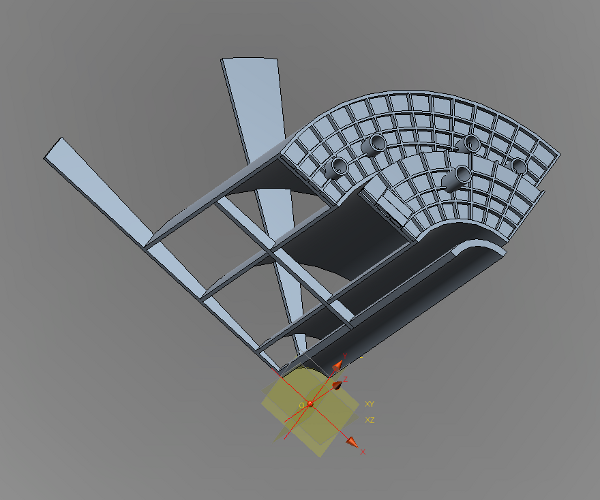
Here is an old version of the cutaway that had a bunch of problems:
Problem 1: The bottom layer had these wedges to hold everything together and provide a solid base. After I started using a raft these were no longer necessary; in fact, they were a detriment because they took a long time to print and the first couple hull layers cooled too much and came apart.
Problem 2: As stated before (C) the cutaway support bar is too wide and takes too long to print.
Problem 3: The lattice is radial instead of square. The printer couldn’t print the off-angle 0.5 mm lines. The lattice would be printed near the edge of the lattice pattern, but there wouldn’t be anything in the middle, and the hull overhang would not get its support.
Problem 4: The circle supports in the lattice are too thin (0.5 mm) and they don’t get printed properly.
Problem 5: The innermost cutaway support is thicker than the others. Once again, there was no benefit to this and it took significantly longer to print than the thinner version in the later versions.


