Tag Archives: reading comprehension

Cravenly resorting to commercial solutions in underwater solenoid valves

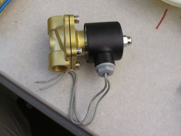
I’m having trouble with the upper valve that will allow air to be released from the hull (thus decreasing buoyancy and giving some downward thrust).  I mean, I’m having trouble with everything, but that’s why I’m doing this, right?  Anyway, I decided to order a couple underwater solenoid valves in the hope that I could stick one in the robot and have it work (hahahahaha).  I found several suppliers in China listed on this site alibaba.com, and settled on Nuoling Pneumatic.  Most of the other options either weren’t waterproof, were too big, didn’t support a 12 V power supply, or had a large minimum order size. The two I bought were $12.35 each, which is less than I was expecting (although the shipping was $55 for two units).

Underwater solenoid valve from Nuoling Pneumatic

Underwater solenoid valve from Nuoling Pneumatic

The valves were a lot bigger and heavier than I expected.  You can see it’s basically a big chunk of brass connected to the waterproof electrical components.  Fortunately it’s easy to take apart:
Continue reading

Un-improving range on the infrared channel

It turned out doing software UART was a terrible idea.  The processor is way too slow to support a reasonable baud rate.  I did figure out how to use a comparator though: the key phrase I was missing was “rail-to-rail.”  That means that inputs can be in the full voltage range from ground to Vcc.  Another handy phrase is “push-pull,” which means that the comparator can output 0 and 1; in contrast, an “open collector” comparator can only output 0, and needs an external resistor to pull the output to 1.

I bought a rail-to-rail push-pull comparator, the MCP6541, and tried it with the receiver circuit, and sure enough it increased the maximum range significantly.  Unfortunately it also increased the minimum range significantly.

Continue reading

Improving range on the infrared channel

The range on the infrared channel, which I discussed in the last entry, is probably enough; but I’d like to increase it a bit.  With more range I can space modules farther apart if needed, and hopefully be able to have a wider angle between the transmitter and receiver.

Fortunately the signal output by the Darlington transistor pair on the receiver is a pretty clean digital signal.  At full power it ranges from (a little above) 0 V to (a little below) 3.3 V.  As the transmitter gets farther away the digital signal remains but the low voltage increases beyond the UART receiver’s ability to read a 0.  For example, at a large distance the UART signal might range from 2.5 V (logical 0) to 3.3 V (logical 1).

There are several options I’ve considered:

Continue reading

How to power an acoustic modem

I mentioned before that I’m basing my acoustic transducer off the Devantech SRF04 ultrasonic ranger.  I’m removing the piezoelectric transducers from a dead SRF04 unit and using them for my modem.  The transducers, which are the part that generate and receive the acoustic pressure wave that carries data, have a range of about 6 metres or so (one way), are driven with up to 20 V, and resonate at around 40 kHz.

The puzzle I’m working on right now is how best to actuate the transducer to generate a 40 kHz pulse.  The SRF04 does it using a chip that’s intended to convert 5 V logic signals into the ±12 V signals used for the RS-232 serial protocol.  Unfortunately most RS-232 converter chips aren’t made to power an acoustic transducer, and they aren’t able to provide enough current to generate a strong signal.

Continue reading