The range on the infrared channel, which I discussed in the last entry, is probably enough; but I’d like to increase it a bit. With more range I can space modules farther apart if needed, and hopefully be able to have a wider angle between the transmitter and receiver.
Fortunately the signal output by the Darlington transistor pair on the receiver is a pretty clean digital signal. At full power it ranges from (a little above) 0 V to (a little below) 3.3 V. As the transmitter gets farther away the digital signal remains but the low voltage increases beyond the UART receiver’s ability to read a 0. For example, at a large distance the UART signal might range from 2.5 V (logical 0) to 3.3 V (logical 1).
There are several options I’ve considered:
The handy old Schmitt trigger is the most straightforward, but it’s touchy to design and it will add a bunch of parts (an op-amp and a bundle of resistors). I tried using a comparator chip, which is like the Schmitt trigger but simpler, but I found that it had a big limitation. It worked, but the inputs can’t exceed Vcc – 1.5 V (the “common mode input voltage range” on the datasheet). It can’t read a digital signal ranging between 1.8 (or more) and 3.3 V, so it would provide some amplification but not a lot. I’m targeting 90% of Vcc as my threshold, so it should read anything below 3.0 V as low. I also considered using another PNP transistor to amplify the difference between Vcc and the input voltage, but: that much amplification is risky noisewise, an extra transistor reduces the bandwidth too much, and the PNP transistor will produce a logically inverted signal.
Another option is to amplify the signal using crazy op-amp magic, but aaaaaaah no.
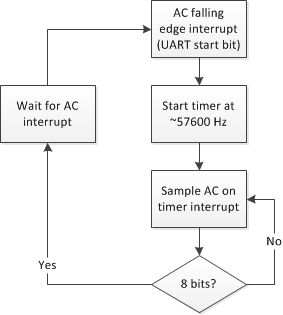
So I tried thinking like I’m supposed to for once, and I’m going to try a software solution. AVR processors include an analog comparator, which I can (hopefully) use to amplify the digital signal coming from the infrared optotransistor. The downside to doing it this way is that it bypasses the UART module, which means that the application needs to receive data manually (I can still use UART to transmit the signal). Receiving data will tie up the processor, but as long as there’s enough time to run the receiver code it should be okay, I don’t foresee much data traffic. Here’s a potential flow chart for the receive procedure:
Some notes:
- The wait process is a euphemism for “disable the timer, store the data, blah blah blah, then go back to the program until the next start bit.” This process takes place during the stop bit, so if there’s another byte incoming then it should finish in time to receive the next start bit.
- Kevin Rosenberg’s awesome tool AVRCalc calculates that the 8-bit timer running at 8 MHz can be used to generate a 57554 Hz interrupt rate using an OCR value of 0x8A.
- I might need to mess around with the timing so that the AC reads the right bit, but probably not. There should be plenty of interrupt overhead delay, and the sampling rate is a little slow and will drift toward the end of the bit.
- I’m not sure how long the analog comparator takes to produce a result but I’m guessing it’s pretty fast because it doesn’t have to do much. The AVR datasheet doesn’t have much information on it. I also don’t know if the comparator has a large common mode input range.
Failing that, I can look for an external comparator with a large common mode input range, or just suck it up and use an op-amp.
