Tag Archives: capacitors

Low-rent acoustic receiver

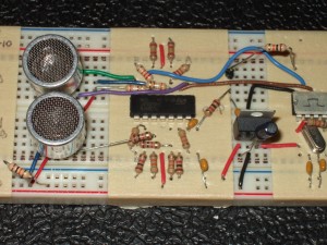
Receiver Circuit

Transmitter (top) and receiver (bottom) circuits.

I’ve previously described the power supply and transmitter for my acoustic modem.

The receiver circuit completes the modem’s hardware design.  It is simply a two-stage amplifier that gives a total gain of about 2000, in series with a band-pass filter.

The acoustic transducer produces a beautiful sine wave with nearly no noise.  I found that I could apply a huge gain to its output and the amplifier’s output would still be clean: the raw (unfiltered) output has a 5 V offset, and the signal fits into the 5 V above the offset.  In other words, the output is at -5 V when idle and peaks at around 0 V when the receiver receives a signal.

The goal is for the receiver to output a signal that is around -10 V when idle and peaks at -5 V when it receives a signal.  These voltages correspond respectively to logic low and high on the microcontroller.
Continue reading

How to power an acoustic modem

I mentioned before that I’m basing my acoustic transducer off the Devantech SRF04 ultrasonic ranger.  I’m removing the piezoelectric transducers from a dead SRF04 unit and using them for my modem.  The transducers, which are the part that generate and receive the acoustic pressure wave that carries data, have a range of about 6 metres or so (one way), are driven with up to 20 V, and resonate at around 40 kHz.

The puzzle I’m working on right now is how best to actuate the transducer to generate a 40 kHz pulse.  The SRF04 does it using a chip that’s intended to convert 5 V logic signals into the ±12 V signals used for the RS-232 serial protocol.  Unfortunately most RS-232 converter chips aren’t made to power an acoustic transducer, and they aren’t able to provide enough current to generate a strong signal.

Continue reading