I’ve covered how not to power an acoustic modem, and how I’d like to power an acoustic modem, now it’s time to tell how I’m doing it right now.
To restate and clarify the problem: I want to use an acoustic transducer to transmit and receive data via pressure waves. The transducer I have transmits a 40 kHz carrier wave, and can be driven by up to 20 V. That means that when transmitting, the circuit must alternate a 20 V signal back and forth between the transducer’s two input pins, once every 25 microseconds. Additionally when receiving, the transducer’s output signal needs to be amplified into a usable signal.
Indulgent aside: When I started doing electronics it took me a while to get an intuitive understanding of voltage. Not so long ago it clicked that when you’ve got a voltage source, as long as you’re careful, you can look at it in whatever way is most convenient. A 20 V power supply is also a ±10 V power supply if you call the voltage at the halfway point “0 V”. This can be quite powerful, for example, if its easier to see one part of a circuit as ranging from -10 V to +10 V and another part of the circuit as ranging from 0 to 20 V. Of course doing so adds a wrinkle to documentation and maintenance, but it can make life easier when you’re thinking about the circuit. (When you’re dealing with power currents (measured in the milliamps rather than the micro- or nanoamps), you also have to consider where the current is flowing and whether or not it’s going to cause noise in the system or blow up your components.)
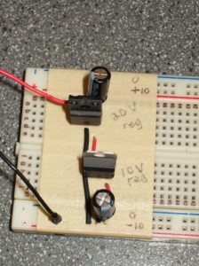
In the image to the left, I have the red and black wire coming in from a variable DC power supply. I have it set to 23 V, which provides plenty of room to regulate to 20 V. This is a drop-in replacement for a few 9 V batteries in series. To reiterate: this is dumb, a better circuit would only need a 5 V power supply, but as an alright man once said, “The way it is is the way it is. We gotta deal with what’s in front of us.”
The 10 V regulator only provides a reference. No current flows from the 20 V rail to the 10 V rail, so the regulator won’t burn out. A better solution would be to use some precisely matched resistors to divide the 20 V in half. That would be a bad idea if the 10 V rail was providing power, because then the voltage drop across the resistors would vary with the current flowing through them. But since it’s only a reference, that’s not a problem. Resistors would be better because each regulator draws several milliamps of current, whereas large resistances would only draw microamps. Alas, I haven’t got precisely matched resistors (see the end of the previous paragraph).
In summary: this approach provides a stable, fairly precise ±10 V power supply. It is perfectly acceptable for now, but in the future it will need to be replaced with a more power-efficient design. Hopefully the final circuit will only require a 5 V power supply, but in the meantime this solution gives me a lot of room for error and lets me move on to other parts of the project.
