The nRF24L01 provides a robust interface for configuring its settings and sending and receiving data. It uses a 4-wire Serial Peripheral Interface (SPI) bus, so the AT90 can communicate with the radio firmware easily using the AVR’s built-in SPI module. The firmware interface is based on a set of registers that can be written to and read from, and several 1-byte instructions for commanding the firmware to perform various tasks. To do something on the nRF24L01, the microcontroller sends an instruction over SPI, usually followed by 1 or more argument bytes. When loading packets onto or off of the radio, the microcontroller must disable the transciever by driving the radio’s CE pin low.
The driver hides the firmware details from applications, but it is useful to understand how the radio works (especially when dealing with bugs in the driver).
Registers
The registers are used to configure the different settings and features that the nRF24L01 has available. Each register (except the three payload registers) has a 5-bit address that is masked into the R_REGISTER and W_REGISTER instructions (see below) respectively to read and write to the register. The following registers are available:
- CONFIG – Configure interrupts, CRC, power, and Tx/Rx status.
- EN_AA – Enable and disable Enhanced Shockburst™ on individual Rx pipes.
- EN_RXADDR – Enable and disable the Rx pipes.
- SETUP_AW – Set the address width.
- SETUP_RETR – Configure the retry delay and number of retries that the radio will use when it doesn’t receive an ack packet.
- RF_CH – Set the RF channel on which the radio broadcasts.
- RF_SETUP – Configure the radio’s on-air data rate, output power, and LNA gain.
- STATUS – Get the interrupt status bits, Tx FIFO full bit, and the number of the pipe that received a packet.
- OBSERVE_TX – Get a count of lost and re-transmitted packets.
- CD – Get the carrier detect bit.
- RX_ADDR_Pn – Set the address for Rx pipe n.
- TX_ADDR – Set the destination address for transmitted packets.
- RX_PW_Pn – Set the static payload width on Rx pipe n.
- FIFO_STATUS – Get the auto-retransmit status, Tx FIFO full/empty, Rx FIFO full/empty.
- ACK_PLD – The payload to send with ack packets, if ack packet payloads are enabled (written to with the W_ACK_PAYLOAD instruction).
- TX_PLD – The Tx FIFO (written to with the W_TX_PAYLOAD and W_TX_PAYLOAD_NO_ACK instructions).
- RX_PLD – The Rx FIFO (read from with the R_RX_PAYLOAD instruction).
- DYNPD – Enable or disable the dynamic payload calculation feature on the Rx pipes.
- FEATURE – Enable or disable the dynamic payload, ack payload, and selective ack features.
FIFOs
There are two packet queues, or FIFOs, in the radio, one for received packets (the Rx FIFO) and one for packets to transmit (the Tx FIFO0. Each FIFO can hold up to three packets. If a transmission fails then the packet is not cleared from the Tx FIFO, it has to be removed using the FLUSH_TX instruction (see below). The Rx FIFO is different from the Rx pipes: a pipe refers to one of the up to six addresses by which the radio can be addressed, whereas the Rx FIFO is the 3-packet queue in which received packets are stored until the microcontroller reads them out of the radio. All six Rx pipes put data into the same 3-packet Rx FIFO.
When the Tx FIFO is full, adding packets to the FIFO pushes the oldest packet out of the queue. When the Rx FIFO is full, new packets are dropped until a space in the FIFO becomes available.
The Tx FIFO is not a true queue. If a receiver is using the ack payload feature then the ack payload is stored in the Tx FIFO. The ack payload is only transmitted in an ack packet though, even if it’s at the head of the FIFO during a transmission. If the ack payload is not at the head of the FIFO and an ack packet is transmitted, then the ack payload is removed from whatever FIFO slot it occupies. As far as I can tell the Rx FIFO behaves like a real queue.
Instructions
The nRF24L01 is controlled using twelve instructions that can be sent over the SPI bus. An instruction must be sent using this process:
- Set CSN low.
- Send the instruction byte.
- If the instruction has arguments, send the argument bytes. If the instruction returns data, send NOP bytes (0xFF) and read in the responses. Arguments are sent with the least-significant byte first, and bytes are sent with the most significant bit first. Endianness issues do not affect normal programming of the radio significantly.
- Set CSN high.
Whenever an instruction is shifted into the radio, the radio’s status register is concurrently shifted back into the AT90.
The nRF24L01 supports the following instructions:
| Instruction | Byte Value | Data Bytes | Description |
| R_REGISTER | 000A AAAA | 1 to 5 | Read the value from the register that has the 5-bit address AAAAA. |
| W_REGISTER | 001A AAAA | 1 to 5 | Write the argument byte(s) to the register that has the 5-bit address AAAAA. |
| R_RX_PAYLOAD | 0110 0001 | 1 to 32 | Read the data payload that is at the head of the Rx FIFO. |
| W_TX_PAYLOAD | 1010 0000 | 1 to 32 | Write the data payload to transmit into the Tx FIFO. |
| FLUSH_TX | 1110 0001 | 0 | Delete all packets from the Tx FIFO. |
| FLUSH_RX | 1110 0010 | 0 | Delete all packets from the Rx FIFO. |
| REUSE_TX_PL | 1110 0011 | 0 | When this instruction is issued, the packet at the head of the Tx FIFO will continually be re-sent. This feature is different fromthe re-transmit used when an auto-ack fails. This report ignores the REUSE_TX_PL feature, and all references to packets
being re-sent refer to a packet being resent due to a packets being dropped when auto-ack is enabled. |
| ACTIVATE | 0101 0000 | 1 | This instruction, when sent with an argument of 0x73, enables the next three instructions. |
| R_RX_PL_WID | 0110 0000 | 1? | When using dynamic payload lengths, this instruction returns the payload size of the packet at the head of the queue.The hardware specification doesn’t have a value in the data byte field, but I assume it returns 1 byte. |
| W_ACK_PAYLOAD | 1010 1PPP | 1 to 32 | Write a payload to include in the next ack packet that will be sent in response to a packet received on Rx pipe PPP. |
| W_TX_PAYLOAD_NO_ACK | 1011 0000 | 1 to 32 | Write the data payload to transmit into the Tx FIFO, and disable auto-ack for only that payload’s packet. |
| NOP | 1111 1111 | 0 | Do nothing (this is used to shift data from the radio to the AT90). |
Radio States
Here is the system state diagram, copied from the nRF24L01 product specification, page 20:
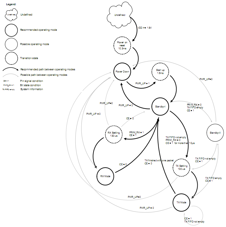
| State | Description |
| Power Down | The PWR_UP bit in the CONFIG register is 0. Register values are maintained in the power down state, and SPI is available. The radio consumes very little power, and can’t transmit or receive data. |
| Standby-I | The CE pin is low and the radio is not transmitting. The radio can’t transmit or receive data. |
| Standby-II | PRIM_RX in CONFIG register is 0 (transmitter enabled), CE is high, but the Tx FIFO is empty. The radio would be in Tx Mode if it had anything to transmit. |
| Rx Mode | PRIM_RX in CONFIG register is 1 (receiver enabled), CE is high. The radio can receive packets. |
| Tx Mode | PRIM_RX in CONFIG register is 0 (transmitter enabled), Tx FIFO is not empty, CE pin is high (see below). The radio is actively transmitting a packet. |
Before loading packets into or out of the radio, the controller must set CE low. This will ensure that the radio properly transitions into Standby-I mode (immediately in the case of Rx mode, or, in Tx mode, once the current transmission completes).
To enter Tx Mode from Standby-I, the controller only needs to pulse CE high for at least 10 μs. In this project CE is held high for the entire transmission.
Timing
There are some important timing requirements that need to be taken into account:
| Situation | M Time |
| Reset (from power off) | 10.3 ms |
| Firmware power up (PWR_UP set in CONFIG register) | 1.5 ms |
| Standby-I or Standby-II to Rx or Tx mode | 130 μs |
| Minimum pulse on CE to begin transmission | 10 μs |
Packet Format
The radio can generate two types of packet: Shockburst™, which is compatible with older versions of Nordic’s radios, and Enhanced Shockburst™, which adds some features to the original format. Enhanced Shockburst™ packets are the same as Shockburst™ packets except for a 9-bit field used for the dynamic payload width and auto-retransmit features. The original format looks like this (source: nRF24L01 product specification, page 44):

In older radios, including the TXRX24G, this packet had a maximum size of 256 bits. The nRF24L01 does not have this constraint except for compatibility with older radios.
The new packet format looks like this (source: nRF24L01 product specification, page 25):

Unlike Shockburst™, Enhanced Shockburst™ allows packets containing no data payload. The control field looks like this (source: nRF24L01 product specification, page 25):
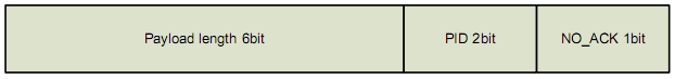
The payload length field is used for the dynamic payload feature. The PID field is a packet identifier. It is incremented every time a new packet it sent, so re-transmitted packets have the same PID as the original. It is used in conjunction with the CRC field to determine if a packet is a re-transmit. If the PID and CRC fields of an incoming packet are equal to those of a packet that has already been received, then the new packet is discarded as a duplicate of the old one. The NO_ACK bit is used for selective ack—if NO_ACK is 1, then the packet is not acknowledged, even if auto-ack is enabled on the receiving pipe.
Interrupts
The radio can generate three interrupts:
- RX_DR – The radio has received a packet.
- TX_DS – The radio has successfully transmitted a packet. If auto-ack is enabled, then this interrupt is triggered when the ack is received. If auto-ack is disabled, then the interrupt is triggered as soon as the packet is on the air.
- MAX_RT – The radio has reached the maximum retries configured in the SETUP_RETR register. In other words, the transmission has failed.
All three interrupts are reflected on the radio’s IRQ pin. The interrupt handler on the controller must read the STATUS register to determine which of the three interrupts was asserted. The TX_DS and MAX_RT interrupts cannot be asserted at the same time, but if an ack packet contains a payload then the RX_DR and TX_DS interrupts are triggered concurrently on the primary transmitter. The Tx FIFO must be cleared using the FLUSH_TX instruction when the MAX_RT interrupt is triggered, or the radio will be unusable.
Examples
Read the RF_STATUS register:
- CSN = 0
- SPDR = 0b00000111 (send instruction to read from RF_STATUS register; thanks to Copper Masud for a correction here)
- Wait for SPI transfer to complete
- SPDR = 0xFF (send a NOP to retrieve the return byte)
- Wait for SPI transfer to complete
- rf_status = SPDR (read the returned byte from the SPI data register)
- CSN = 1
Read the STATUS register:
- CSN = 0
- SPDR = 0xFF (send NOP instruction; STATUS register is shifted back to the master whenever the master sends an instruction)
- Wait for SPI transfer to complete
- status = SPDR
- CSN = 1
Read and write the CONFIG register
- CSN = 0
- SPDR = 0b00000000 (send instruction to read from CONFIG register)
- Wait for SPI transfer to complete
- SPDR = 0xFF (send a NOP to retrieve the return byte)
- Wait for SPI transfer to complete
- config = SPDR
- CSN = 1
- Do something with config
- CSN = 0
- SPDR = 0b00100000 (send instruction to write to CONFIG register)
- Wait for SPI transfer to complete
- SPDR = config (send the instruction parameter, which is the value to be written to the register)
- Wait for SPI transfer to complete
- CSN = 1