Roomba
The iRobot Roomba vacuum cleaner robot is an excellent mobile platform, giving the hobbyist easy control over its motors, sensors, and vacuum unit. All Roombas manufactured since 2005 have a serial port interface that accepts a male 7-pin mini-DIN connector, allowing the Roomba to communicate with a device running UART at TTL levels (0-5 V). The figure below shows the Roomba’s serial port with a mini-DIN connector. Beneath the serial port is the battery charger plugin. The mini-DIN interface is described on page 2 of the Roomba SCI specification manual [PDF].

In addition to the serial port lines, the mini-DIN port provides a Device Detect (DD) pin, used to turn the Roomba on and configure the default baud rate, and a direct line to the Roomba’s battery output and ground.
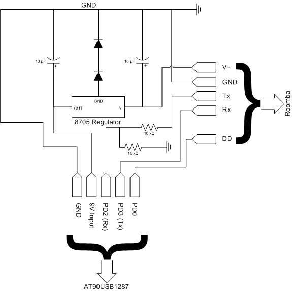
The Roomba UART port operates at 5 V, so some care needs to be taken when interfacing it with a 3.3 V device such as the AT90. The signal generated by the Roomba on its Tx pin can cause excessive current draw in an AT90. A voltage divider should be placed between the Roomba’s Tx pin and the AT90’s Rx pin to shift the Roomba’s signal level from 5 V to around 3.3 V. The voltage divider is shown in the circuit diagram below, using a 15 kΩ resistor and a 10 kΩ resistor to scale the signal by 3/5 (thus the signal read by the AT90 is at 3 V). For a microcontroller running at 5 V this precaution is not necessary. The following table shows the pinout for our Roomba serial adapter along with the colour of the corresponding wire on the adapter’s ribbon cable:
| Pin | Colour | Function |
| DD | Blue | Device Detect. Active low. When the Roomba is powered down, holding this pin low for 500 ms will turn on the Roomba. |
| NC | This position is non-connected. It can be used as a key position to make sure that the V+ pin isn’t put into the DD receptacle. | |
| Rx | Green | The Roomba’s UART receive pin. This is connected to the AT90’s Tx pin (PD3). It doesn’t need a level shifter. |
| Tx | Yellow | The Roomba’s UART transmit pin. This is connected to the AT90’s Rx pin (PD2). It does need a level shifter as described above. |
| GND | Orange | The Roomba battery’s negative terminal. |
| V+ | Red | The Roomba battery’s positive terminal. The V+ voltage can range from 15 V to 17 V depending on the battery charge. It should be regulated to power the AT90. |

The Roomba battery outputs about 16 V of unregulated direct current, so while it is possible to power the AT90 from the serial port, the power supply needs to be regulated and filtered. There are several ways to regulate the Roomba’s battery supply to a level suitable for powering the AT90. A complete discussion of the power supply options is beyond the scope of this report. The best solution is to supply power to the AT90’s 9 V power input. The 9 V input is connected to an onboard 5V regulator, so it can accept any voltage higher than around 6 V. We use a 5 V regulator and two diodes to regulate the battery power down to around 6.2 V.

The GND pin on the regulator doesn’t sink any current—it is only used as a reference—so the diodes don’t block any current flow. The diodes create a voltage drop of about 0.6 V each, so the regulator’s GND pin sits at 1.2 V above the system’s common ground. The regulator output is set to 5 V above the GND pin reference, which is 6.2 V referenced to the common ground. Raising the voltage is necessary to accommodate the drop-out voltage for the AT90’s 5 V regulator.
The DD pin is labelled as connected to PD0 on the AT90, but it can be connected to any general I/O pin.
The electrolytic capacitors on the regulator’s input and output act as voltage filters and stabilizers on the regulator input and output pins. When the voltage on the regulator’s input and output pins is constant, the capacitors act as open circuits (no current flows through them). If the input or output voltages change relative to the common ground, then the capacitors resist the change. This resistance to change filters out transients in the voltages. The AT90 9 V input is regulated twice to lower voltages (once to 5 V and once to 3.3 V), so highly reliable filtering isn’t critical for our purposes. Also, the regulator is being powered by the Roomba’s 16 V battery so there is no ripple voltage that needs to be filtered like there would be with an AC supply. A capacitor should still be used to filter the output voltage because it’s far away from the power source and subject to external interference.
Other Microcontroller Boards
Porting the Roomba driver to other AVR-based boards (e.g. the Seeeduino or ATmega256) should be pretty easy. You will probably need to change the UART driver (or perhaps replace it, e.g. with Arduino’s Serial class), and the Rx and Tx pins will probably be different. You can find out what the Rx and Tx pins are supposed to be on the board’s documentation. If you’re using a raw AVR chip, the chip’s hardware specification will show the Rx and Tx pins in the section on pin configurations.