Strobe Guitar Tuner r2 Design Changes

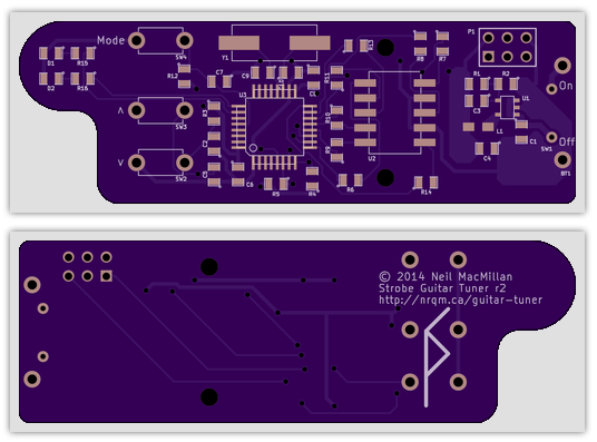
Circuit board rendered by oshpark.com.

Circuit board rendered by OSH Park.

I’ve learned a bunch about making circuit boards at work recently, so I decided to re-do the ol’ strobe guitar tuner project from 3 or 4 years ago.  The original still works… sort of.  I have to power it from a 3x AA battery holder that’s clipped to the power terminals with alligator clips.  It doesn’t tune the low E string properly for some reason.  The input’s inflexible, and it’s hard to reprogram.

The hardware has been updated in the following ways:

Continue reading

Robotic Monochord Guitar Version 1.0

More like version 0.1, every part of it was bad in some way.  We did robotic self-tuning monochords—single-string musical instruments—last spring in the mechatronics class.  The students did pretty well.

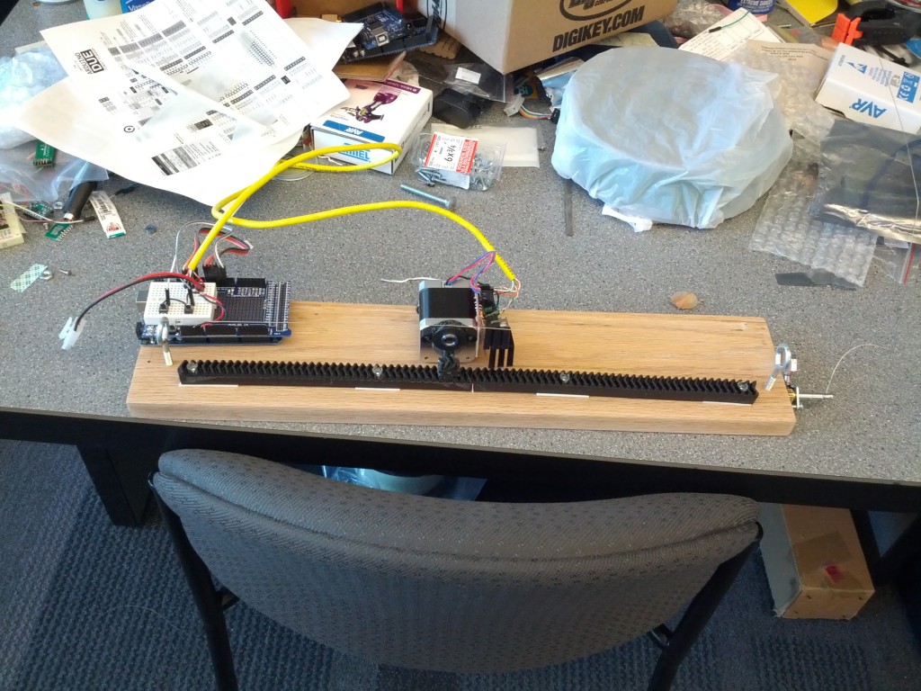
Most of their robots were designed along similar lines: they had a servo with a pick to pluck the string, an electric guitar pickup from which the robot read the string’s frequency, and a stepper motor to spin a machine head to adjust the string’s tension (and thereby change the frequency).  The design had some issues that the students didn’t have time to fix before they had to move on to their next projects.  We found that the biggest problem was that the tension controls weren’t responsive.  The machine heads are made more for precision than speed—with a guitar you have to tune a string precisely, but you shouldn’t have to do it very often so it doesn’t matter if it’s slow.  One team adjusted the tension using a linear actuator that stretched the string by moving a bar back and forth, which was a novel idea but which also suffered from unresponsiveness since they necessarily used a lead screw as a linear actuator.

I figure a robot should be inherently precise compared to a human, so machine heads are the wrong tool for the job.  We ought to be able to find a speedier way of adjusting the string frequency.  Instead of adjusting the tension I wanted to try adjusting the string length like you do with your fingers in most real stringed instruments.

First try at a guitarbot.

First try at a guitarbot.

Continue reading

AVR Code for the MS5541C Pressure Sensor

I originally wrote code for the MS5541C pressure sensor using bit banging, and described the result of my investigation in the previous log entry.  At the end I mentioned that the sensor’s weird digital interface is kind of like SPI, and looks SPI-compatible, with several differences that could be worked around.  The most notable difference was that reading and writing data happen out of phase with respect to the serial clock edge. It wound up being a little squirrellier than that, but it worked out.  Below is some code for accessing the MS5541C with SPI. It runs on a Seeeduino Mega (which is compatible with the Arduino Mega and uses the ATmega1280 microcontroller), but I’ve eschewed the Arduino libraries for the sake of more control (and, for the ol’ bit-banging, better timing resolution). Some of the code, particularly the SPI stuff, could be replaced with Arduino library calls.
Continue reading

Interfacing AVR/Arduino with the MS5541C pressure sensor

The MS5541C is kind of an oddball sensor, BUUUUUUUT it’s small, it can be used underwater (with appropriate waterproofing), it’s cheapish (~$30), and Digikey sells it. It’s a pain to get running though, because of its hardware interface (50 mil pitch, surface mount (and not the good kind of surface mount either)) and its data interface (which doesn’t implement any particular standard protocol).

I tried carving out an interface board using some copper-clad PCB and a rotary tool, but I didn’t do a good job and it was really hard to get the 50 mil pads to line up with the messily-carved copper traces.  I used a heat gun to solder the sensor onto the PCB, and it almost worked—but two of the pins were shorted.  And of course a copper pad got torn off of the sensor when I tried to remove it from the PCB.  I bought another one and connected it to a 100 mil header via some ribbon cable.  That’s the wrong thing to do.  The datasheet specifies that the sensor should be securely fastened to a circuit board to prevent it from flexing, although it hints that might be just to prevent stress on the solder pads (which are, as previously noted, not incredibly strong) and not necessary to improve sensor performance.  The spec also says that a 47 μF tantalum decoupling capacitor should be placed as closely as possible to the sensor.  That is a noise reduction requirement, but whatever, there’s one on the Arduino that I have the sensor hooked up to and that’s good enough for now.  In any case, eucatastrophically, it works.

The data interface is a little easier to work out.  Like I said before, it doesn’t use a standard protocol, presumably to keep the internal circuitry as uncomplicated (and small and low-power) as possible.  The thankfully decent datasheet defines the protocol using electrical timing diagrams, and fortunately it’s simple enough once you work through it:

Continue reading

Waterproofing 3D Prints (and also making them look super-cool) with Epoxy Clay

It’s pretty hard to get a watertight object out of our Makerbot Thing-O-Matic.  The walls of printed objects are pretty solid, but unexpectedly porous; even a thick block printed with 100% infill will allow water to penetrate it due to errors around the edges and imperfectly fused strands of plastic.  If you want to make a hollow object waterproof you’re going to have to do some post-processing.

It gets worse when the object is a curved surface, as is my AUV hull.  I’ve read that objects can be made watertight by adding outer shells.  That may be true for some objects, but on objects that curve along the z-axis the number of shells exposed to the surface grows as the tangent plane gets closer to parallel to the printer’s build platform—and big holes start to form.

My hull doesn’t actually have to be watertight, it’s a wet hull.  But it has to be airtight in order to hold the bubble of gas that controls the robot’s buoyancy.  Here’s what the airtight hull looks like:

Continue reading

Underwater Solenoid Valve Remake

I tried a solenoid I scavenged from underwater valves on my 3D printed valve system and it didn’t work (duh).  It was just too weak.  The original valve spreads the force from the high-pressure side across a larger area, so I guess the spring return can be comparatively weak.  My design didn’t do that.  I also didn’t cut my compression spring down very much, but I qualitatively determined that the solenoid wasn’t generating a useful amount of force by holding it on the magnetic core while turning the power on and off a bunch of times.  I am a terrible engineer.

So I went back to square 2 and decided to remake the original brass valve body in lighter ABS plastic using our Makerbot 3D printer.  The beta version looked like this: Continue reading

Cravenly resorting to commercial solutions in underwater solenoid valves

I’m having trouble with the upper valve that will allow air to be released from the hull (thus decreasing buoyancy and giving some downward thrust).  I mean, I’m having trouble with everything, but that’s why I’m doing this, right?  Anyway, I decided to order a couple underwater solenoid valves in the hope that I could stick one in the robot and have it work (hahahahaha).  I found several suppliers in China listed on this site alibaba.com, and settled on Nuoling Pneumatic.  Most of the other options either weren’t waterproof, were too big, didn’t support a 12 V power supply, or had a large minimum order size. The two I bought were $12.35 each, which is less than I was expecting (although the shipping was $55 for two units).

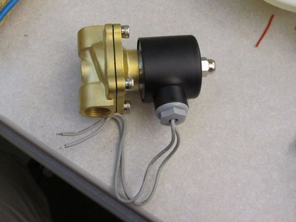
Underwater solenoid valve from Nuoling Pneumatic

Underwater solenoid valve from Nuoling Pneumatic

The valves were a lot bigger and heavier than I expected.  You can see it’s basically a big chunk of brass connected to the waterproof electrical components.  Fortunately it’s easy to take apart:

Continue reading

Un-improving range on the infrared channel

It turned out doing software UART was a terrible idea.  The processor is way too slow to support a reasonable baud rate.  I did figure out how to use a comparator though: the key phrase I was missing was “rail-to-rail.”  That means that inputs can be in the full voltage range from ground to Vcc.  Another handy phrase is “push-pull,” which means that the comparator can output 0 and 1; in contrast, an “open collector” comparator can only output 0, and needs an external resistor to pull the output to 1.

I bought a rail-to-rail push-pull comparator, the MCP6541, and tried it with the receiver circuit, and sure enough it increased the maximum range significantly.  Unfortunately it also increased the minimum range significantly.

Continue reading

Improving range on the infrared channel

The range on the infrared channel, which I discussed in the last entry, is probably enough; but I’d like to increase it a bit.  With more range I can space modules farther apart if needed, and hopefully be able to have a wider angle between the transmitter and receiver.

Fortunately the signal output by the Darlington transistor pair on the receiver is a pretty clean digital signal.  At full power it ranges from (a little above) 0 V to (a little below) 3.3 V.  As the transmitter gets farther away the digital signal remains but the low voltage increases beyond the UART receiver’s ability to read a 0.  For example, at a large distance the UART signal might range from 2.5 V (logical 0) to 3.3 V (logical 1).

There are several options I’ve considered:

Continue reading