I tried a solenoid I scavenged from underwater valves on my 3D printed valve system and it didn’t work (duh). It was just too weak. The original valve spreads the force from the high-pressure side across a larger area, so I guess the spring return can be comparatively weak. My design didn’t do that. I also didn’t cut my compression spring down very much, but I qualitatively determined that the solenoid wasn’t generating a useful amount of force by holding it on the magnetic core while turning the power on and off a bunch of times. I am a terrible engineer.
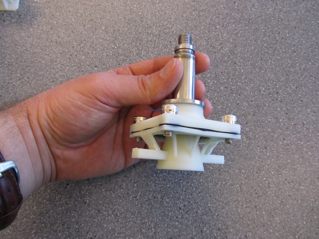
So I went back to square 2 and decided to remake the original brass valve body in lighter ABS plastic using our Makerbot 3D printer. The beta version looked like this:
I re-used the gasket, screws, core, and shaft from the original valve (where the solenoid sits), and replaced the big brass parts with light ABS plastic that is customized to fit onto my hull. The steel shaft press-fits onto the shaft holder at the top of the photo. The shaft holder screws into the connector piece, which implements the same idea as the brass valve piece, but instead of the input being a pipe fitting the input is open to the inside of the robot hull. Note that in the photo I’m holding the valve upside-down, the solenoid shaft will hang down from the top of the robot hull, and the other end of the valve will bolt onto the hull’s top using the existing screw holes, pressing the base of the conical shaft against the hull’s top hole (apparently I’m a terrible photographer too). When the valve opens, the air inside the hull will flow through the conical shaft out of the hull’s top hole and will be replaced by water flowing in through the bottom hole.
The new valve did in fact work. The solenoid successfully pulled back the gasket to open the valve when activated, and it almost sealed when the power was disconnected. The seal wasn’t perfect because it printed over a bump in the 3D printer’s build platform. The plastic was 277 grams less massive than the original brass, and with a tweak or two the new valve will bolt onto the hull efficiently.
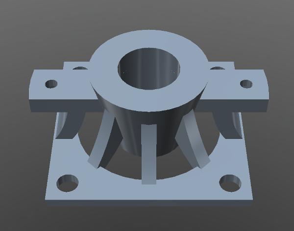
The valve had a few problems. The steel shaft’s wide screw part was too wide for the hole it was supposed to screw into, so I had to file the hole out until I could press-fit the shaft in. The support structures on the interface piece are too spindly, as you can see in the photo. Also the square plate on the interface piece was a little thin, and it sat a little too short. The corners of the square hit other structures inside the robot hull, and it needed to be about 1 mm farther away from the nut holders. In the new version I have tried to rectify these issues:
The square plate is now half again as thick, and the nut holders (the bits sticking out near the top of the conical shaft) are 1 mm farther away from the plate. The supports are a lot thicker, too: they’re 4 mm wide instead of 2 mm, and the six supports that don’t connect to the nut holders flare outward stylishly.
There’s one other issue that I foresee. The heavy copper solenoid and the steel shaft/magnetic core sit pretty high in the hull, and raise the robot’s centre of mass. This is a potential problem because if the centre of mass is too high the robot will roll too much in the water. I can add extra ballast to lower the centre of mass, which may or may not be fine, depending on what kind of buoyancy the rest of the hull has. I might actually have to do some engineering to figure that out. Or, I can try it and see what happens.

