Tag Archives: transducers

Improving range on the infrared channel

The range on the infrared channel, which I discussed in the last entry, is probably enough; but I’d like to increase it a bit.  With more range I can space modules farther apart if needed, and hopefully be able to have a wider angle between the transmitter and receiver.

Fortunately the signal output by the Darlington transistor pair on the receiver is a pretty clean digital signal.  At full power it ranges from (a little above) 0 V to (a little below) 3.3 V.  As the transmitter gets farther away the digital signal remains but the low voltage increases beyond the UART receiver’s ability to read a 0.  For example, at a large distance the UART signal might range from 2.5 V (logical 0) to 3.3 V (logical 1).

There are several options I’ve considered:
Continue reading

Poor man’s IrDA for intermodular communication

If all goes extraordinarily well, the AUV will have the following modules sitting in the hull:

  • Acoustic modem
  • Motor control
  • Depth control (buoyancy control and pressure sensing)
  • Master controller

Rather than wiring everything together, I plan to give each module its own power supply and use an optical communication protocol to connect the modules to the master controller.  The inside of the hull will be cleaner and more solid than if everything was wired together, and waterproofing will be easier.  Here’s how it works:

Continue reading

Lots of Neat Options for an Acoustic Transducer

I mentioned the US40KT-01 transducer pair from Meas Spec before, but it’s an air sensor.  One could cover it with a potting compound to waterproof it.  My source suggested 3M Scotchcast 2130, which is intended for electrical insulation but apparently has some desirable acoustic properties (viz being close to the acoustic impedance of water).  He cites Acoustic and dynamic mechanical properties of a polyurethane rubber [PDF] by Mott, Roland, and Corsaro as a good resource on this stuff, but I haven’t read it yet.

I also came across some really cheap waterproof transducers that may be suitable.  Unfortunately they both have high directivity, whereas I’d like at least an omnidirectional transmitter.  Another possible issue is that they’re made for outdoor applications, not underwater applications.  How waterproof is “waterproof”?

This guy has a super-cool post on driving the little waterproof transducers.  Instead of using a step-up transformer, he uses an inductor and a MOSFET.  The inductor gets charged from a 9 V battery through the MOSFET.  When the MOSFET is opened the magnetic field collapses and it sends about 300 mA of current through a diode to power the transmitter.  This is called the inductive flyback method.  Awesome!

One final note: I found what look like the transducers that are on the ranger modules I’m using.  Less than US$3 per pair.

Low-rent acoustic receiver

Receiver Circuit

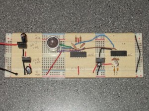
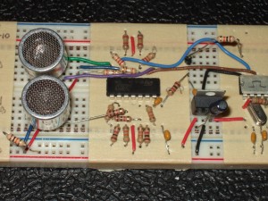
Transmitter (top) and receiver (bottom) circuits.

I’ve previously described the power supply and transmitter for my acoustic modem.

The receiver circuit completes the modem’s hardware design.  It is simply a two-stage amplifier that gives a total gain of about 2000, in series with a band-pass filter.

The acoustic transducer produces a beautiful sine wave with nearly no noise.  I found that I could apply a huge gain to its output and the amplifier’s output would still be clean: the raw (unfiltered) output has a 5 V offset, and the signal fits into the 5 V above the offset.  In other words, the output is at -5 V when idle and peaks at around 0 V when the receiver receives a signal.

The goal is for the receiver to output a signal that is around -10 V when idle and peaks at -5 V when it receives a signal.  These voltages correspond respectively to logic low and high on the microcontroller.

Continue reading

Low-rent acoustic transmitter

Acoustic transmitter circuit

Acoustic transmitter circuit.

Above you can see the transmitter part of my acoustic modem.  From left to right, the components are: the power supply, the acoustic transducer, the amplifier, and the microcontroller.

The problem: I need to send a 40 kHz, 20 V peak-to-peak square wave to the transducer.  The circuit has two outputs, + and -, that are connected to the two transducer pins.  In other words, each output needs to switch from +10 V to -10 V  and back once every 25 microseconds.

As always, there are a few decent solutions, and as always I didn’t implement the best one.

Continue reading

How to power an acoustic modem

I mentioned before that I’m basing my acoustic transducer off the Devantech SRF04 ultrasonic ranger.  I’m removing the piezoelectric transducers from a dead SRF04 unit and using them for my modem.  The transducers, which are the part that generate and receive the acoustic pressure wave that carries data, have a range of about 6 metres or so (one way), are driven with up to 20 V, and resonate at around 40 kHz.

The puzzle I’m working on right now is how best to actuate the transducer to generate a 40 kHz pulse.  The SRF04 does it using a chip that’s intended to convert 5 V logic signals into the ±12 V signals used for the RS-232 serial protocol.  Unfortunately most RS-232 converter chips aren’t made to power an acoustic transducer, and they aren’t able to provide enough current to generate a strong signal.

Continue reading