Category Archives: Acoustic Modem

Lots of Neat Options for an Acoustic Transducer

I mentioned the US40KT-01 transducer pair from Meas Spec before, but it’s an air sensor.  One could cover it with a potting compound to waterproof it.  My source suggested 3M Scotchcast 2130, which is intended for electrical insulation but apparently has some desirable acoustic properties (viz being close to the acoustic impedance of water).  He cites Acoustic and dynamic mechanical properties of a polyurethane rubber [PDF] by Mott, Roland, and Corsaro as a good resource on this stuff, but I haven’t read it yet.

I also came across some really cheap waterproof transducers that may be suitable.  Unfortunately they both have high directivity, whereas I’d like at least an omnidirectional transmitter.  Another possible issue is that they’re made for outdoor applications, not underwater applications.  How waterproof is “waterproof”?

This guy has a super-cool post on driving the little waterproof transducers.  Instead of using a step-up transformer, he uses an inductor and a MOSFET.  The inductor gets charged from a 9 V battery through the MOSFET.  When the MOSFET is opened the magnetic field collapses and it sends about 300 mA of current through a diode to power the transmitter.  This is called the inductive flyback method.  Awesome!

One final note: I found what look like the transducers that are on the ranger modules I’m using.  Less than US$3 per pair.
Low-rent acoustic receiver

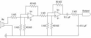
Receiver Circuit

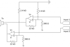
Transmitter (top) and receiver (bottom) circuits.

I’ve previously described the power supply and transmitter for my acoustic modem.

The receiver circuit completes the modem’s hardware design.  It is simply a two-stage amplifier that gives a total gain of about 2000, in series with a band-pass filter.

The acoustic transducer produces a beautiful sine wave with nearly no noise.  I found that I could apply a huge gain to its output and the amplifier’s output would still be clean: the raw (unfiltered) output has a 5 V offset, and the signal fits into the 5 V above the offset.  In other words, the output is at -5 V when idle and peaks at around 0 V when the receiver receives a signal.

The goal is for the receiver to output a signal that is around -10 V when idle and peaks at -5 V when it receives a signal.  These voltages correspond respectively to logic low and high on the microcontroller.

Continue reading

Low-rent acoustic transmitter

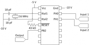
Acoustic transmitter circuit

Acoustic transmitter circuit.

Above you can see the transmitter part of my acoustic modem.  From left to right, the components are: the power supply, the acoustic transducer, the amplifier, and the microcontroller.

The problem: I need to send a 40 kHz, 20 V peak-to-peak square wave to the transducer.  The circuit has two outputs, + and -, that are connected to the two transducer pins.  In other words, each output needs to switch from +10 V to -10 V  and back once every 25 microseconds.

As always, there are a few decent solutions, and as always I didn’t implement the best one.

Continue reading

How I’m powering my acoustic modem

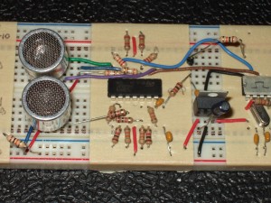
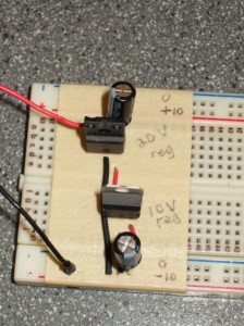
Power supply

A ±10 V power supply

I’ve covered how not to power an acoustic modem, and how I’d like to power an acoustic modem, now it’s time to tell how I’m doing it right now.

To restate and clarify the problem: I want to use an acoustic transducer to transmit and receive data via pressure waves.  The transducer I have transmits a 40 kHz carrier wave, and can be driven by up to 20 V.  That means that when transmitting, the circuit must alternate a 20 V signal back and forth between the transducer’s two input pins, once every 25 microseconds.  Additionally when receiving, the transducer’s output signal needs to be amplified into a usable signal. Continue reading

How to power an acoustic modem

I mentioned before that I’m basing my acoustic transducer off the Devantech SRF04 ultrasonic ranger.  I’m removing the piezoelectric transducers from a dead SRF04 unit and using them for my modem.  The transducers, which are the part that generate and receive the acoustic pressure wave that carries data, have a range of about 6 metres or so (one way), are driven with up to 20 V, and resonate at around 40 kHz.

The puzzle I’m working on right now is how best to actuate the transducer to generate a 40 kHz pulse.  The SRF04 does it using a chip that’s intended to convert 5 V logic signals into the ±12 V signals used for the RS-232 serial protocol.  Unfortunately most RS-232 converter chips aren’t made to power an acoustic transducer, and they aren’t able to provide enough current to generate a strong signal.

Continue reading

How not to power an acoustic modem

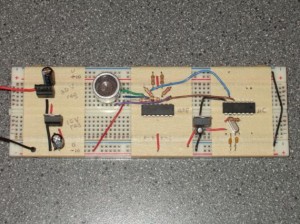
crummy power supply

How not to generate a ±10 V power supply

I feel pretty dumb talking to nobody like this.  My domain name doesn’t even work yet, but I guess logging is what engineers do.  And I’m imaginative enough to see the utility of it: it’ll be nice down the line to have a log to review, writing stuff down helps flesh out ideas, and an open design process will make it a heck of a lot easier to produce open documentation.  It will be tough to expose all my bad decisions and half-baked ignorance (and mixed metaphors), but I can suck it up.

My first project is to build an acoustic modem.  This follows the principle of multiplying work: the modem doubles as my class project for ELEC 571: Underwater Acoustics.  We’ve been using the Devantech SRF04 ultrasonic ranger in the mechatronics lab, and it strongly informs my design.  The SRF04 actually uses an RS-232 chip to generate ±9 V levels, which actuate a piezoelectric transducer.  I took a couple of the transducers from a broken SRF04 to use for my project.

I tried using an RS-232 chip that we had lying around in the lab, but those things have draconian current limits.  There’s no way I can power a whole circuit off of one.  I’m probably going to try it again soon though.

My solution: a DC/DC converter (AP34063N8L) to step up a 7.4 V lithium polymer battery up to 20 V.  Taking half the output as the reference voltage will produce a ±10 V power supply.  With that I can power pretty much anything I want. Continue reading