I’ve previously described the power supply and transmitter for my acoustic modem.
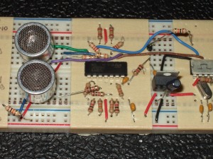
The receiver circuit completes the modem’s hardware design. It is simply a two-stage amplifier that gives a total gain of about 2000, in series with a band-pass filter.
The acoustic transducer produces a beautiful sine wave with nearly no noise. I found that I could apply a huge gain to its output and the amplifier’s output would still be clean: the raw (unfiltered) output has a 5 V offset, and the signal fits into the 5 V above the offset. In other words, the output is at -5 V when idle and peaks at around 0 V when the receiver receives a signal.
The goal is for the receiver to output a signal that is around -10 V when idle and peaks at -5 V when it receives a signal. These voltages correspond respectively to logic low and high on the microcontroller.
The band-pass filter serves two functions: a blocking capacitor (the simplest kind of high-pass filter) removes the 5 V DC component, and a low-pass filter removes the 40 kHz carrier wave. The filter also has a side-effect of attenuating the signal, so that the filter’s output peaks at 1 V instead of 5 V (this is bad). The attenuation problem can probably be avoided, either by tuning the filter better (I’m not sure how), or by replacing the DC blocking capacitor with a diode or something that drops 5 V, or by subtracting 5 V from the output with a difference amplifier. From now on I discuss the output of the filter, not the raw unfiltered amplifier output.
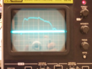
You can see the receiver’s output in the photo above. Unfortunately my screen capture technology is unsophisticated. The output peaks at just over 1 V (due to the filter attenuation), and lasts for about 3 ms (recall that the 40 kHz carrier signal is filtered out, so it’s just one big chunk of signal). The waveform corresponds to a very strong input into the receiver: I held a piece of paper about a foot above the modem and transmitted an acoustic ping with the transmitter. The waveform looks somewhat different when the received signal is weaker:
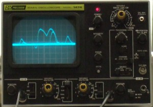
This corresponds to the piece of paper being held a metre or so away from the transmitter. There is a dip in the middle of the signal, and a lone tertiary peak a little more than 0.5 ms after the original wave ends. As the acoustic signal gets weaker, this dip gets more pronounced. This is caused by ringing in the receiver transducer’s piezoelectric sensor.
As I mentioned in my post on the transmitter component, the transmitter encodes a 1 bit of data as eight acoustic pulses at 40 kHz (a 0 bit is simply encoded as no signal). The total duration of the acoustic signal is 200 μs; clearly this is much less than the 3 ms output observed at the receiver. What happens is that when the acoustic signal is received, the receiver starts to resonate, like a guitar string.
It takes 8 pulses for the receiver’s piezoelectric crystal to reach full resonance. Once the acoustic signal stops, the crystal continues to resonate, until after 3 ms the energy finally dissipates and the crystal goes quiet. I’m not totally sure what’s going on, but I think the dips are caused when the resonance somehow interferes with itself; you can observe this phenomenon in many resonance effects. Eventually the resonance gets back into phase with itself (or whatever) and reinforces itself for a while.
Anyway, the good news is that even at large distances (>10 metres) the acoustic receiver can pick up the transmitted signal effectively, and the receiver’s output includes a strong peak that fits reliably in a 3 ms window. This means that for data transmission, one bit can be sent every 3 ms, for a total bit rate of 333 bits per second. This is a low data rate, but not so much lower than that of commercial modems. I’ll write more about data transmission later.


