I originally wrote code for the MS5541C pressure sensor using bit banging, and described the result of my investigation in the previous log entry. At the end I mentioned that the sensor’s weird digital interface is kind of like SPI, and looks SPI-compatible, with several differences that could be worked around. The most notable difference was that reading and writing data happen out of phase with respect to the serial clock edge. It wound up being a little squirrellier than that, but it worked out. Below is some code for accessing the MS5541C with SPI. It runs on a Seeeduino Mega (which is compatible with the Arduino Mega and uses the ATmega1280 microcontroller), but I’ve eschewed the Arduino libraries for the sake of more control (and, for the ol’ bit-banging, better timing resolution). Some of the code, particularly the SPI stuff, could be replaced with Arduino library calls.
Continue reading
Tag Archives: crazy stuff
Un-improving range on the infrared channel
It turned out doing software UART was a terrible idea. The processor is way too slow to support a reasonable baud rate. I did figure out how to use a comparator though: the key phrase I was missing was “rail-to-rail.” That means that inputs can be in the full voltage range from ground to Vcc. Another handy phrase is “push-pull,” which means that the comparator can output 0 and 1; in contrast, an “open collector” comparator can only output 0, and needs an external resistor to pull the output to 1.
I bought a rail-to-rail push-pull comparator, the MCP6541, and tried it with the receiver circuit, and sure enough it increased the maximum range significantly. Unfortunately it also increased the minimum range significantly.
The Schmitt trigger

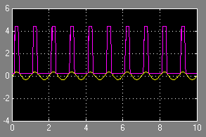
Simulation of a Schmitt trigger. The yellow sine wave is the input, the purple square wave is the output.
I was looking for a way to convert an analogue signal into a digital signal, and came across the Schmitt trigger. This is a great little circuit that you can build with a couple transistors or with an operational amplifier. I tried to build a transistor-based simulation in Simulink, but it didn’t work right away. My op-amp simulation did work, so I stuck with that.
The principle is simple: if the trigger input rises above a certain threshold, then the output saturates to the op-amp’s positive power supply voltage. When the input falls below another threshold, the output saturates to the op-amp’s negative power supply voltage. If the input lies between the thresholds then the output doesn’t change from whatever it was before.
This is incredibly useful. To the left you can see a 0.3 V sine wave being converted into a 5 V binary signal (actually a 4.5 V signal, since I added a diode in series with the output to keep it from going down to -5 V). It also effectively filters out any input jitter that doesn’t cross the threshold needed to change the output state. Microcontrollers have Schmitt triggers on their digital inputs. For example, an AVR microcontroller being powered by 5 V typically considers a 0 logic level to be under 1.5 V and a 1 logic level to be over 3 V. If the input sits between 1.5 V and 3 V then the digital state remains whatever it was before the input entered that region.
Alas, it’s not a perfect circuit. I used an online calculator to figure out what resistances I needed for my project. Configurations that worked in the calculator and in simulation didn’t work in reality, either producing no output or something more like a sawtooth wave than the square wave I expected. It’s probably a limitation in my op-amp—maybe the signal is too high-frequency, I didn’t investigate very deeply.