The MS5541C is kind of an oddball sensor, BUUUUUUUT it’s small, it can be used underwater (with appropriate waterproofing), it’s cheapish (~$30), and Digikey sells it. It’s a pain to get running though, because of its hardware interface (50 mil pitch, surface mount (and not the good kind of surface mount either)) and its data interface (which doesn’t implement any particular standard protocol).
I tried carving out an interface board using some copper-clad PCB and a rotary tool, but I didn’t do a good job and it was really hard to get the 50 mil pads to line up with the messily-carved copper traces. I used a heat gun to solder the sensor onto the PCB, and it almost worked—but two of the pins were shorted. And of course a copper pad got torn off of the sensor when I tried to remove it from the PCB. I bought another one and connected it to a 100 mil header via some ribbon cable. That’s the wrong thing to do. The datasheet specifies that the sensor should be securely fastened to a circuit board to prevent it from flexing, although it hints that might be just to prevent stress on the solder pads (which are, as previously noted, not incredibly strong) and not necessary to improve sensor performance. The spec also says that a 47 μF tantalum decoupling capacitor should be placed as closely as possible to the sensor. That is a noise reduction requirement, but whatever, there’s one on the Arduino that I have the sensor hooked up to and that’s good enough for now. In any case, eucatastrophically, it works.
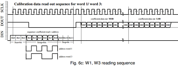
The data interface is a little easier to work out. Like I said before, it doesn’t use a standard protocol, presumably to keep the internal circuitry as uncomplicated (and small and low-power) as possible. The thankfully decent datasheet defines the protocol using electrical timing diagrams, and fortunately it’s simple enough once you work through it:

Example timing diagram for reading W1 and W3 calibration words from the MS5541C internal ROM, copied from the datasheet.
There are six 16-bit data words that can be read over the MS5541C’s data interface (there are no writable words). Four calibration words hold six constant values awkwardly packed together. The other two words are to obtain the temperature and pressure measurements. The diagram above shows the waveform diagram for reading two of the data calibration words, W1 and W3. The waveform for the W2 and W4 words is identical except the rising edge that precedes the data signal on DOUT happens 1 clock cycle sooner. The waveform for triggering the temperature and pressure measurements is also similar, and has a 33 ms conversion delay whose completion is signaled as a falling edge on DOUT. You can look at the datasheet for more details on the protocol’s specifics.
You might look at that diagram and notice it’s a lot like an 8-bit SPI protocol, with a few subtle differences. Well observed, hypothetical reader! I think the protocol should be implementable using SPI, with these caveats:
- The command pattern on DIN is 12 bits (10 bits for the temperature/pressure read commands, and 16 for the reset command). This isn’t a problem, the command word can be padded out to 16 bits and sent as two bytes.
- The sensor doesn’t send anything back on commands, and sends back data when receiving 0 bits. No problem, just send 0 bytes to read the slave output and ignore the output when writing commands.
- There’s no select pin, so you can’t put the sensor on an SPI bus unless you turn the sensor on and off at its power source. This is fine as long as there’s nothing else on the SPI bus.
- The DIN and DOUT pins are read 180° out of phase. This is potentially a problem.
To elaborate on the fourth point, the sensor reads command bits from DIN (viz MOSI) on rising clock edges and returns data bits to DOUT (viz MISO) on falling clock edges. In the AVR’s version of SPI data in either direction are always valid on the same clock edge: the rising edge by default, or, if the SPI module’s clock polarity bit is reversed, on the falling edge. Hey, that suggests a solution to the 4th item:
You ought to be able to toggle the SPI module’s polarity bit between transmitting and receiving, so that the master transmits data on the rising edges and receives data on the falling edges.
I’ve implemented the code by bit banging because I didn’t notice the SPI similarity until I was done doing it manually. It’s a mess. When I’ve got the SPI version working I’ll put up some code.
