It turned out doing software UART was a terrible idea. The processor is way too slow to support a reasonable baud rate. I did figure out how to use a comparator though: the key phrase I was missing was “rail-to-rail.” That means that inputs can be in the full voltage range from ground to Vcc. Another handy phrase is “push-pull,” which means that the comparator can output 0 and 1; in contrast, an “open collector” comparator can only output 0, and needs an external resistor to pull the output to 1.
I bought a rail-to-rail push-pull comparator, the MCP6541, and tried it with the receiver circuit, and sure enough it increased the maximum range significantly. Unfortunately it also increased the minimum range significantly.
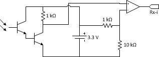
Here’s the circuit diagram for the modified receiver circuit:
The 1 kΩ and 10 kΩ resistors are in a voltage divider configuration to generate a 3.0 V reference against which the input is compared. If the input is higher than 3.0 V, the comparator outputs 3.3 V, and otherwise the comparator outputs 0 V.
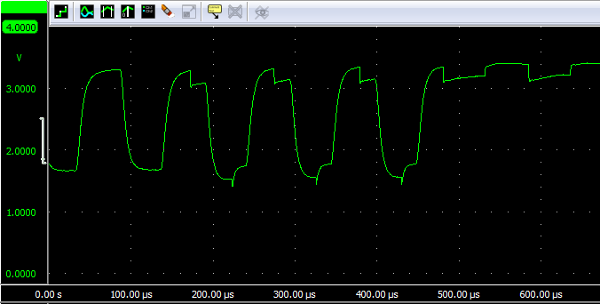
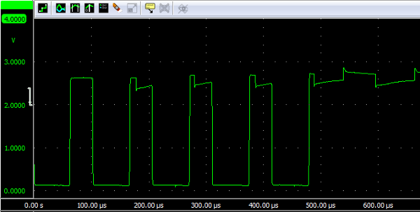
I guess there are a bunch of transistors inside the comparator, and putting them in a chain with the pair of external transistors messes things up. I don’t know why, but it might be a gain-bandwidth thing (too much gain, lowers the maximum frequency the circuit can operate at). This is what the output looks like at about 6.5 cm:
The jagged bits aren’t there without the comparator. I used the U character to test because its binary pattern is 01010101. As you can see, the pattern is there but it’s kind of messed up and it’s dangerously close to 3.0 V. (Now that I look at this again I see maybe reducing the 3.0 V threshold would improve the minimum range.)
I figured I could put an OPA2134 op-amp voltage follower in between the external transistors and the comparator. This would de-couple the two sets of transistors, so the weird transistor chaining effect would disappear. This worked perfectly, once, for no apparent reason at all. Eventually, after spending a day trying to reproduce my success, I read the op-amp’s datasheet more closely and discovered that it’s not rail-to-rail and should never have worked (it can’t output the full 3.3 V signal, so the comparator’s input was never reaching 3.0 V).
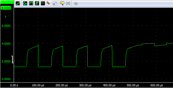
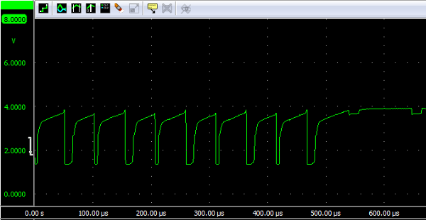
I switched to a JFET op-amp that had rail-to-rail output, and it was able to transmit the ‘U’ character at a good set of ranges, both small and large. Unfortunately this is the signal it was outputting, at 7.5 cm and at 2 cm:
The observant among you, my imaginary audience, will notice two strange things from this screenshot:
- The signal is peaking at almost 4 V.
- It’s sending 9 bits at 7.5 cm and 19 bits at 2 cm.
Hoo boy, it didn’t work at all, and it was pure luck that the ‘U’ transmitted correctly at short range (followed, presumably, by a framing error that my system silently ignored). No other character worked.
I found out that you can use an op-amp as a comparator, so I tried that with my OPA2134:
Okay! You can see what it means that the amplifier is not rail-to-rail, it’s only going up to 2.6 V (and that only briefly), but if I remember correctly it received. Unfortunately the high bits got narrower for some reason as the range decreased, so it didn’t actually do anything to solve the range problem.
I tried using the JFET amp as a comparator, but it didn’t output anything at all so I gave up and ignored the project for a few weeks. My current solution is to pretend there isn’t a problem, and if I run into the minimum range issue then I can just bend the receiver askew so that the signal is damped enough to receive. In the meantime, the transmitter now has a wider field of view, which ought to make it easier to place several receivers in range of the control unit.
