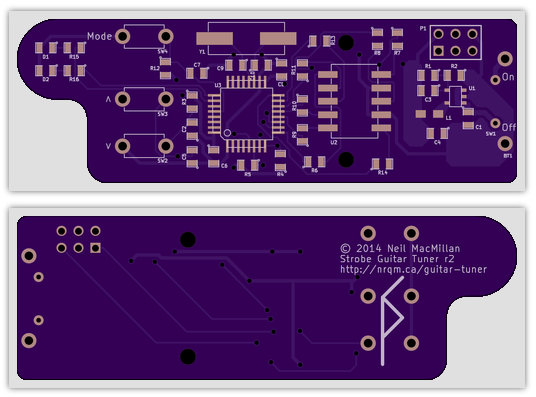
Circuit board rendered by OSH Park.
I’ve learned a bunch about making circuit boards at work recently, so I decided to re-do the ol’ strobe guitar tuner project from 3 or 4 years ago. The original still works… sort of. I have to power it from a 3x AA battery holder that’s clipped to the power terminals with alligator clips. It doesn’t tune the low E string properly for some reason. The input’s inflexible, and it’s hard to reprogram.
The hardware has been updated in the following ways:
- I’ve learnt how to use KiCAD for circuit design. It’s a lovely open source EDA tool that handles schematic design, layout, and automated trace routing. ExpressPCB was okay for the original tuner, but this board is a bit more complicated, complicated enough that laying the circuit out manually would be difficult, tedious, and error prone. Plus I need to output gerber files, because…
- … I’m going to get the PCBs manufactured instead of etching them manually. At work I needed 24 little boards manufactured for a project and went with OSH Park. I was very happy with the outcome OSH Park is a great batch service, they can make two-layer boards with silkscreen and soldermask for a reasonable price in low volumes. The main downside is their lead time is around a month. I also considered circuits.io, which seems like a really cool idea, but their design tools seem rudimentary (or maybe I’m just not accustomed to them), they use OSH Park on the back end so they’re more expensive, and they don’t allow full control over the board’s source files (that is, you can’t download them in gerber format).
- The battery supply has been changed from a coin cell to 2x AAA batteries. The battery holder will mount on the back of the board. I’m a little concerned that it won’t be as comfortable to hold as the old version, we’ll see. Battery life is also suspect, I figure a pair of AAAs should last something over 10 hours. Is that long enough? Probably, right? It’s only going to be on for a few minutes at a time and I can program in an automatic shut-down if it gets left on.
- There’s a real power switch that will disconnect the battery instead of putting the MCU to sleep.
- There’s a switching regulator now. I added the regulator, configured to output around 2 V, so that all the LEDs are delivered a constant current over the lifetime of the batteries. Without the regulator the LEDs get dimmer as the batteries drain. I chose a switching regulator instead of a linear regulator mainly because it’s cool and I’ve never used a switching regulator before. Also it has a very low dropout (about 0.05 V) and will be more efficient for most of the battery’s lifetime. Fun fact: the first regulator I chose was the only cheap 2.0 V fixed-output switching regulator on Digikey, but I failed to notice at first that it’s 1.5 mm long and 1 mm wide. It fits six surface mount pads in that area, and has no leads. I’m not soldering that by hand, but I applaud its existence. Well played, Texas Instruments.
- There’s a 6-pin PDI port for programming the microcontroller in the circuit. As you can see the MCU is a TQFP chip that’s soldered directly to the board, so a programming port is necessary. It would be cool to get a USB-capable MCU so that tunings can be set from a host computer without reprogramming the board, but that’s a feature for the 2018 version.
- I spent a long time trying to figure out the human-device interface. My original tuner just had a 6-way switch to select one of the six notes in the standard guitar tuning. I wanted the interface to be flexible enough to support multiple tunings–not that I’m a competent enough guitar player to need multiple tunings, but it seems like a good idea nonetheless. I considered two rows of LEDS, one to indicate the current note and one to indicated the selected tuning. I also considered a dual 7-segment LED display to display the selected note in scientific pitch notation (e.g. E2, A2, G3, D3, B3, E4). Finally I settled on a single 7-segment display, which I thought was pretty clever until I went back and looked at the project my original tuner is based on and discovered that’s what they’d done in the first place. The user controls the tuner with two buttons to navigate up and down, and one button to switch mode between tuning select and note select. Again, how comfortable will be to operate the switches one-handed while holding the tuner without risking electrostatic discharge in the components next door is an open question.
- The MCU is an ATxmega8E5. I’m coming around to the xmega line, although it’s kind of caught in the middle between ARM and the old megas. The xmega library is more sensible than the mega’s library, the xmega has more features, and it costs about the same as an equivalent mega. Originally I intended to use an ATSAMD20E14A, one of Atmel’s newish ARM Cortex-M0+ chips. They look like nice MCUs and cost about the same as an equivalent mega/xmega. One of the reasons I started this project was to get some experience with ARM. Unfortunately that chip (and other ARM chips I looked at) has a maximum current output of 3 mA on I/O pins when powered with 2 V, so it’s really not suitable for an application that boils down to turning a bunch of 10 to 20 mA LEDs on and off. The xmegas allow 25 mA per pin.
Next step: reviewing and tweaking the PCB design and ordering a few boards. They should be here in a month or so.